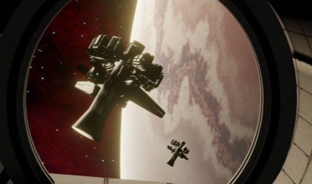
As you can probably tell from some of my other posts, science fiction and space are a passion. I created the scene below in 2021 using Blender and an asset I’d bought from the DAZ Studio marketplace. The asset I’d bought was the window. Everything else was mine.
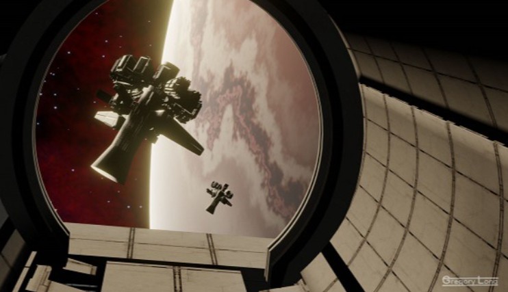
This post is about the planet that you can see. How I made it. To be honest, I made it mostly through watching lots of videos of other people trying to make planets. So I want this post to explain what is actually happening – the whys and wherefores – instead of merely the what.
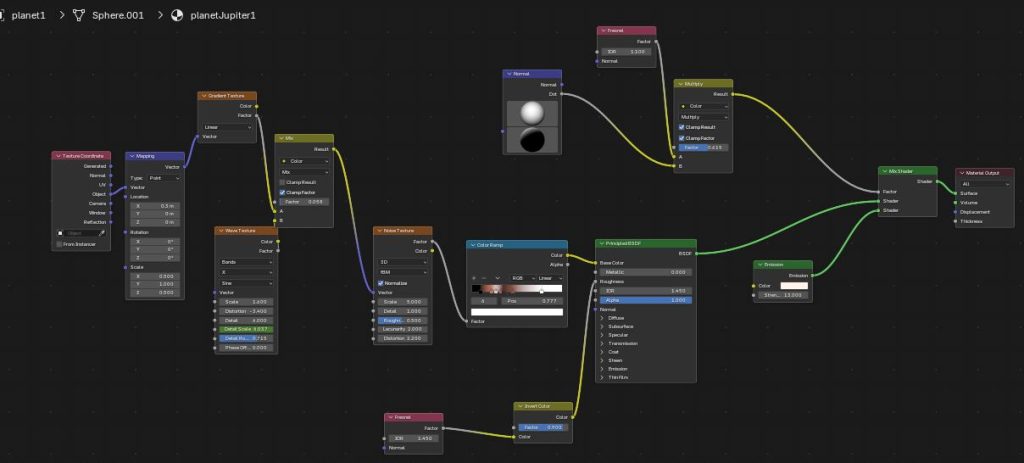
Behold – this is the planet material.
So let’s try to understand it.
Base Mapping & Coordinate Setup
Think of procedural texturing in Blender like wrapping a patterned sheet of gift paper around a 3D object, except instead of physical paper, the computer uses mathematical instructions to draw the pattern directly onto the surface.
Before Blender can draw any pattern (like cloud stripes or noise), it needs to know where to put it. A Texture Coordinate node acts like a built-in GPS for your 3D model.
Generated Coordinates: When you pick “Generated” coordinates, Blender looks at the overall outer shape of your sphere and creates an invisible 3D grid around it, ranging from 0 to 1 along the X (left/right), Y (forward/back), and Z (up/down) axes. It basically tells Blender: “Start drawing the pattern from one edge of the sphere and stretch it evenly to the opposite edge.”
The Mapping node then acts like a modifier attached to that GPS signal. It lets you move, rotate, or stretch the invisible coordinate grid before any colors or patterns are drawn on top of it.
Why Scale ($X=0.5, Y=1.0, Z=0.5$)?
In Blender’s mapping system, scaling down the coordinate numbers actually stretches the visual pattern out across the surface.
- The Math Metaphor: Imagine a grid with markings every 1 inch. If you change the scale factor to $0.5$, you are telling Blender to stretch those grid lines out so they are now 2 inches apart.
- The Visual Result: By cutting the X and Z coordinate scales in half ($0.5$), the grid stretches horizontally around the equator of the sphere. Instead of getting tight, perfectly square spots of noise or vertical streaks, the patterns get squished and elongated sideways — giving the long, horizontal stretching look seen in planetary cloud bands (like Jupiter’s atmospheric belts).
Imagine you are an artist painting a giant gas planet. Instead of using a paintbrush, you are layering different mathematical “recipes” on top of each other to create stormy, swirling clouds. Here is how that step-by-step process works:
Gradient Texture (The Direction Guide): A gradient is simply a smooth fade from light to dark (or 0 to 1) across a surface. Here, it creates a smooth directional ramp across the sphere. Think of it as establishing a baseline direction (like North-to-South or West-to-East) so the computer knows which way the planet’s atmospheric currents should generally travel.
Wave Texture (The Atmospheric Bands): A Wave Texture generates repeating light and dark stripes across your object, much like the stripes on a zebra or a candy cane. Here it creates the raw horizontal bands of clouds you see on planets like Jupiter.
- The Settings:
- Scale ($1.4$): Controls how many bands appear. A lower number keeps the bands wide and thick.
- Distortion ($-3.4$): Warps the straight stripes so they look wavy, turbulent, and natural rather than rigid and artificial.
- Detail ($4.0$): Adds tiny wrinkles and jagged edges along the wave borders so they look like complex cloud edges rather than smooth, painted lines.
Mix Node (The Secret Swirl Trick): A Mix node takes two inputs and blends them together, controlled by a “Factor” slider (where $0.0$ means 100% of the first item, and $1.0$ means 100% of the second item). Here, instead of using the Mix node to blend colors on the screen, this setup uses it to blend coordinates (the directional map). By taking the Gradient and mixing in just a tiny amount of the Wave Texture (Factor: $0.058$), it gently bends the grid lines. It acts like a slight breeze pushing the coordinate map sideways before the next node sees it.
Noise Texture (The Fluid Storms): A Noise Texture creates random, splotchy cloud shapes—similar to looking down at real earth clouds or marble patterns. Here it generates the main fine detail of the planet’s atmosphere (the small swirls, eddies, and fluid-like storms).
- The Settings:
- Scale ($5.0$): Sets the overall size of the storm splotches.
- Detail ($1.0$): Keeps the surface look relatively smooth and fluid-like, preventing it from looking like rough sandpaper.
- Distortion ($2.2$): Twists the random spots into spinning, stretched-out swirls.
How they work here is that instead of feeding clean, straight coordinates into the Noise Texture, the setup distorts the map using the Wave and Gradient first. Because the Noise node receives a pre-swirled grid, its random splotches get stretched into long, stormy belts that wrap naturally around the planet.
A Color Ramp takes a black-and-white image and replaces the dark, gray, and light areas with custom colors. Think of it like a “color-by-number” system where $0$ (pure black) gets painted one color, $1$ (pure white) gets painted another, and all the grays in between get smooth gradient shades. Up to this point, the node graph has only produced a abstract black-and-white pattern of waves and noise. The Color Ramp takes that grayscale pattern and maps it to planet colors:
- Dark spots in the noise become deep mocha browns.
- Mid-gray spots become rich orange-reds.
- White spots become light cream tones.
This color result is plugged straight into the Base Color socket of the Principled BSDF (the main shader material), effectively laying down the colored paint skin of the gas giant.
Fresnel & Invert Color (The Surface Gloss Trick):
- Fresnel (Index of Refraction / IOR): In real life, objects look glossier when you view them at a steep angle than when you look straight at them. (For example, look straight down at a wooden floor and it looks matte; tilt your head down near the floor and look across it, and you see bright reflections). The Fresnel node calculates this view-angle math for 3D shapes.
- Roughness Socket: In Blender, a value of $0.0$ (black) means hyper-glossy like a mirror, while $1.0$ (white) means completely dull/matte like chalkboard.
- So we set the following:
- Fresnel Node ($\text{IOR } 1.450$): Outputs a white ring along the outer edges of the sphere and a dark center, because the edges are angled away from your eyes.
- Invert Color Node (Factor: $0.900$): Flips that calculation upside down! Now, the center of the sphere is bright (high roughness value), and the extreme outer edges are dark (low roughness value).
When plugged into Roughness, this makes the center face of the planet look soft, matte, and diffuse (like dense, light-absorbing atmosphere), while the very edges taper into a smooth, slightly glossy sheen. It softens the hard 3D sphere look and gives the planet a sense of depth and atmospheric haze.
Normal & Fresnel (The Edge Isolator): When looking at planets from space, the atmosphere appears as a thin, glowing ring clinging to the silhouette of the globe.
- Normal Node: Defines a directional vector to control how the light calculations align with the curve of the sphere.
- Fresnel Node ($\text{IOR } 1.100$): Acts as a silhouette detector. By setting a very low Index of Refraction ($\text{IOR } 1.100$), it creates a mask that is completely black across the front of the sphere, turning white only at the extreme outer edge.
Mix / Multiply (The Dimmer Switch): In node math, multiplying a mask by a number less than $1.0$ acts like a dimmer switch to dial back intensity. Here it takes the edge mask from the Fresnel node and scales its strength down using a factor of $0.615$. This softens the mask so the resulting atmosphere looks like a subtle, natural gas haze rather than a harsh white border.
Emission Shader (The Light Source): Standard shaders need an external sun or lamp to illuminate them. An Emission Shader generates its own light directly—behaving like a neon sign or a glow stick. So this creates a vibrant blue-white light source set to a high brightness (Strength: 13.0), simulating backlit gases shining at the edge of space.
Mix Shader (The Master Composite): A Mix Shader takes two fully painted materials and layers them together based on an overlay mask.
- Input 1: The main planet body (the stormy cloud belts, noise, and color ramp).
- Input 2: The self-illuminated blue Emission glow.
- Factor Socket: Driven by the Fresnel edge mask.
The Final Result is that the center of the sphere displays the solid, textured planet surface. As your eye moves toward the outer edges, the shader smoothly transitions to the self-illuminated blue emission light—producing a vibrant, atmospheric glow around the planet.